White Paper • Sep 2026
Powering India's 5G Future
How Class 4 Fault-Managed Power Systems (FMPS) Solve the Densification, Cost, and Safety Challenges of Next-Generation Telecom Infrastructure
Document Version:** 3.0 | Date: September 2026 Published by:** AberCXO (www.abercxo.com | hello@abercxo.com)
Executive Summary
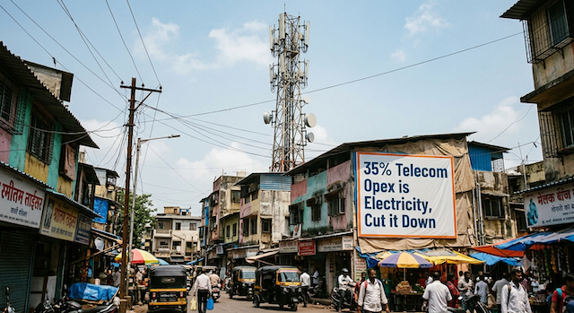
The rapid expansion of 5G networks across India hinges on a critical operational imperative: network densification. Delivering high-speed, ultra-low-latency connectivity demands the deployment of thousands of Remote Radio Heads (RRHs) and small cells spaced just hundreds of meters apart.
However, traditional power delivery models present severe operational and economic bottlenecks. Conventional AC or low-voltage DC distribution architectures incur high capital expenditure (CapEx), complex cabling requirements, extended deployment schedules, and elevated maintenance risks.
This white paper details how Class 4 Fault-Managed Power Systems (FMPS) resolve these structural challenges. By transmitting up to 400 V DC over lightweight, touch-safe, Class 4 cabling, FMPS provides telecom operators and infrastructure providers with a scalable, cost-effective, and safe power architecture.
1. The 5G Densification Dilemma: Legacy Power Bottlenecks
5G deployment introduces three fundamental architectural power challenges:
1.1 Voltage Drop Over Remote Distances
5G high-frequency signals require dense small-cell grids. Delivering standard 48V DC power across extended distances—such as in airports, transit systems, or tech parks—causes substantial voltage drop. Compensating for this drop necessitates heavy, expensive copper cabling, driving up material costs and structural load.
1.2 Conduit and Permitting Bottlenecks
Traditional AC deployments require certified electricians, rigid steel or PVC conduits, and extensive structural core-drilling. These steps add significant labour overhead and delay project timelines by months.
1.3 Distributed Battery Degradation
Installing localized Uninterruptible Power Supply (UPS) batteries at each individual remote cell creates maintenance vulnerabilities. Batteries placed in unconditioned ceiling voids or outdoor cabinets experience rapid thermal degradation, driving up operational expenditure (OpEx).
2. Technical Solution: Class 4 Fault-Managed Power
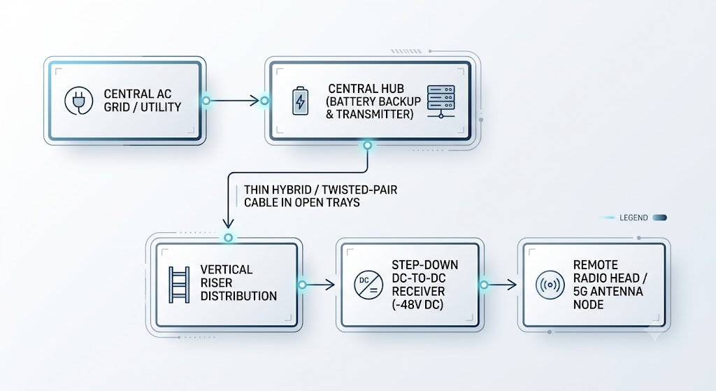
Class 4 Fault-Managed Power Systems fundamentally alter power distribution by delivering continuous DC power with concurrent fault monitoring—not by transmitting energy in discrete packets.
Operational Mechanism
| Phase | What Happens |
|---|---|
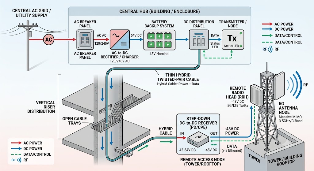
| 1. Centralized Conversion | A central transmitter converts AC or DC input to 400 V DC for distribution. |
| 2. Continuous DC Delivery | Power is delivered continuously over Class 4 certified cabling—not in packets. |
| 3. Concurrent Fault Monitoring | The system continuously monitors line integrity, detecting open circuits, shorts, or human contact in real time. |
| 4. Millisecond Shutdown | If a fault is detected, energy transmission halts within milliseconds, mitigating shock and arc flash hazards. |
Core Infrastructure Advantages
- Rapid Fault Detection & Shutdown: The system interrupts power within milliseconds if a fault is detected—with appropriate installation procedures and a validated migration plan.
- Improved Conversion Efficiency: Powers native telecom equipment directly, reducing redundant conversion stages. Actual savings depend on the existing power architecture and must be validated per site.
- Reduced Physical Footprint: Uses thin, flexible Class 4 cabling that reduces weight and tray space requirements in dense environments.
- Centralized Energy Storage: Enables consolidation of battery infrastructure into climate-controlled rooms—reducing thermal degradation and replacement frequency. (Requires site-specific validation.)
- ![][image1]
3. Regulatory Positioning in the Indian Ecosystem
Navigating India's regulatory framework—divided between the Department of Telecommunications (DoT), TRAI, municipal bodies, and the Chief Electrical Inspectorate (CEIG)—requires strategic positioning.
3.1 Classification as Telecom Transmission Equipment
By integrating transmitters within centralized telecom equipment rooms and receivers inside Remote Radio Head housings, the system can be positioned as an integrated telecom subsystem. This structural approach aligns with Power-over-Ethernet (PoE) architectures. However, any proposed exemption from building electrical codes requires documented support from the relevant authorities.
3.2 Touch-Safe Design
Class 4 FMPS is designed with rapid fault detection and shutdown. This addresses field technician safety by mitigating arc flash and electrocution hazards. Installation responsibilities and personnel qualifications depend on the work involved and local requirements in India.
4. Strategic Market Execution Playbook
To accelerate adoption against legacy providers in India, deployment strategies should target specific high-impact segments:
4.1 Target Infrastructure Companies (InfraCos)
Engage tower infrastructure providers—such as Indus Towers and Brookfield (Data Infrastructure Trust)—who manage physical asset rollouts and prioritize copper cost reductions and deployment speed.
4.2 Deploy in Mega-Infrastructure Venues
Target large-scale developments including greenfield airports and metro rail networks where running heavy conduit through complex architecture is impractical.
4.3 Centralize Energy Storage
Consolidate battery infrastructure into climate-controlled main equipment rooms. Eliminating decentralized edge batteries can lower replacement frequency and improve grid reliability—subject to site-specific validation.
5. What This White Paper Does Not Claim
To ensure accuracy and compliance with product specifications, this white paper does not claim:
- Absolute safety or blanket elimination of electrical hazards
- Guaranteed zero downtime
- Packet scheduling, peer-to-peer energy trading, or seamless solar/storage integration as confirmed capabilities
- Reuse of ordinary data cables or existing low-voltage cables without project-specific validation
- Blanket savings percentages (all savings figures must be validated per site)
6. Next Steps
This white paper is an educational document. For product-specific specifications, ROI modeling, and pilot design, AberCXO will work with the designated technology partner and execution partner to build a validated, site-specific business case.
Contact: hello@abercxo.com | www.abercxo.com