White Paper • Sep 2026
The AI Power Paradox
Density, Cost, and Sustainability: The Three Forces Reshaping India's Data Centre Power Architecture
Document Version: 1.2 | Date: September 2026 Published by: AberCXO (www.abercxo.com | hello@abercxo.com)
Executive Summary
Every megawatt of AI compute in India requires not just power—but water. Every rack deployed adds conversion losses that become heat, and every unit of heat must be removed by a cooling system that consumes even more. The result: more compute, more water, more carbon, less efficiency.
This is the AI Power Paradox.
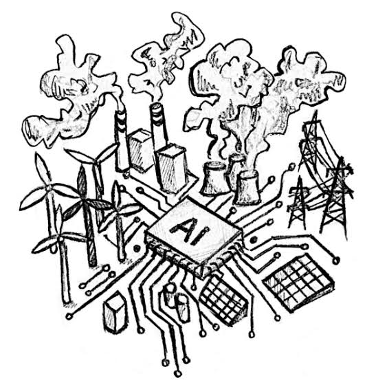
The rapid expansion of AI and cloud infrastructure in India hinges on a critical operational imperative: data centre densification. Rack power densities have surged past 100 kW, and India's total data centre capacity is projected to grow from ~1,500 MW in 2025 to 13.56 GW by 2031-32. Delivering reliable, efficient, and scalable power to thousands of GPU-dense racks demands a fundamental rethink of data centre power architecture.
Traditional AC power delivery models present severe operational and economic bottlenecks. Conventional AC or low-voltage DC distribution architectures incur high capital expenditure (CapEx), complex cabling requirements, extended deployment schedules, and elevated energy losses.
This white paper details how Class 4 Fault-Managed Power Systems (FMPS) resolve these structural challenges. By transmitting up to 400-450 V DC over lightweight, touch-safe, Class 4 cabling, FMPS provides data centre operators with a scalable, cost-effective, and safe power architecture that eliminates redundant conversion stages, reduces copper usage, and accelerates deployment.
1. The AI Data Centre Dilemma: Legacy Power Bottlenecks
AI deployment introduces four fundamental architectural power challenges:
1.1 The AC/DC Conversion Tax
Every conversion from AC to DC and back again wastes energy. In a conventional AC data centre, power goes through a transformer, UPS double-conversion, PDU step-down, and server PSU—each stage losing energy. 18% to 28% of the power delivered to a 100 kW AI rack can be lost as heat before it reaches the data center racks. This wasted energy must be removed by cooling systems, compounding the loss.
1.2 The Copper and Cable Burden
At 48V DC, high current requires thick, heavy copper cables. As rack power density increases, traditional AC distribution architectures are reaching their physical limits—both thermally and in terms of the sheer mass of copper required. Voltage drop over distance forces the use of even heavier cables, driving up material costs and structural load.
1.3 The Cooling Conundrum
AI workloads generate far more heat than traditional IT. Cooling alone can consume 30–40% of a data centre's total electricity in air-cooled facilities. For high-density GPU clusters, the heat generated by power conversion losses adds to an already challenging thermal load.
1.4 The Deployment Velocity Gap
Data centre construction timelines are under pressure to match the pace of AI demand. Traditional power infrastructure—conduit, breakers, junction boxes, and certified electricians—adds months to deployment schedules. Every week of delay is lost revenue.
1.5 The Environmental Paradox
The AI Power Paradox isn't just about cost. It's about resources.
The Conversion Tax Becomes an Environmental Tax
Traditional AC data centre infrastructure loses 10–30% of incoming energy through multiple conversion stages—AC from the grid stepped down, converted to DC for storage, inverted back to AC for distribution, and converted again to DC at the chip level. This "conversion tax" creates a double penalty: energy lost as heat requires additional cooling, consuming more energy.
For a 100 MW data centre, this means 10–30 MW is dissipated as heat before reaching a single GPU. That heat must be removed—and removing it costs more energy.
The Water Dimension: India's Critical Resource
India's data centres consumed an estimated 150 billion litres of water in 2024–25. By 2030, that figure is projected to more than double to 358 billion litres annually.
The arithmetic is stark:
| Metric | Value |
|---|---|
| Water per MW per year | 25 million litres (Karnataka IT Minister, March 2026) |
| Daily water per 100 MW | ~2 million litres |
| Water consumption per kWh | 1.5–2.5 litres (evaporative cooling) |
| Projected 2030 consumption | 358 billion litres annually |
The critical constraint: Nearly 75% of India's data centres are already located in water-stressed regions. Rajasthan extracts 147.11% of its annual groundwater recharge—the second highest rate in the country. Several groundwater assessment units in Maharashtra are classified as semi-critical. Hyderabad's surface water supply dropped 20% during summer 2024. Mumbai's reservoirs stood at just 44.5% of capacity in March 2026.
This is not a future problem. It is a present one.
The Air-Cooling Trap
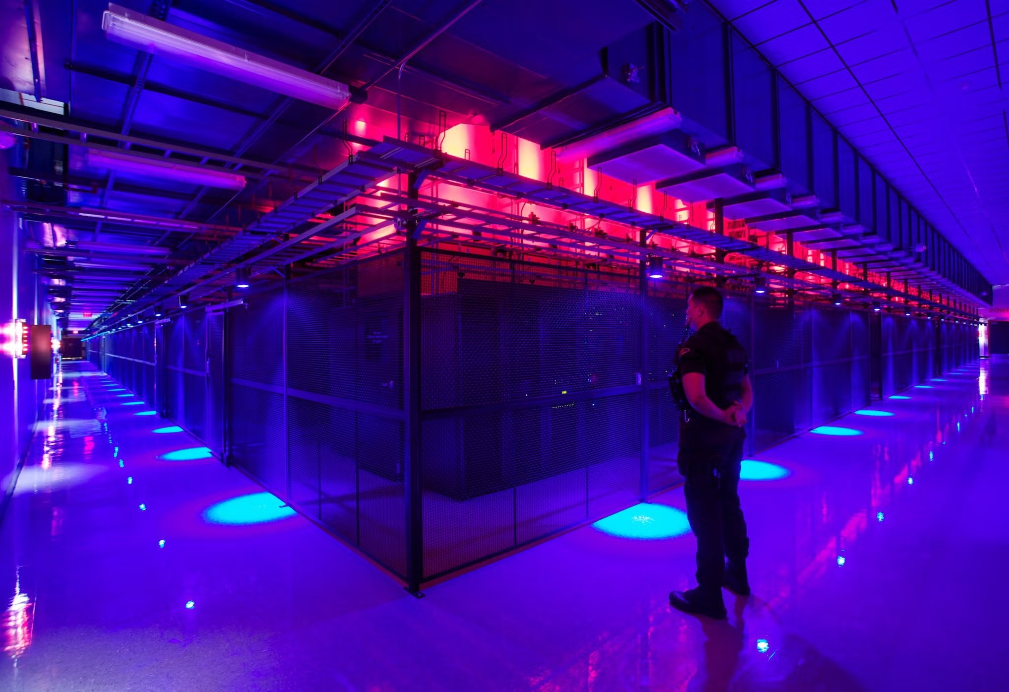
Traditional air cooling was designed for 5–15 kW racks. Modern AI racks now hit 120 kW+, with next-generation systems targeting 150–600 kW per rack.
At these densities, air cooling becomes both technically limited and environmentally costly:
| Cooling Method | PUE Range | Cooling Energy Share |
|---|---|---|
| Traditional air cooling | 1.5–1.8 | 30–40% of total electricity |
| Air with economizers | 1.3–1.5 | Reduced but still significant |
| Direct-to-chip liquid cooling | 1.1–1.25 | 40–50% less cooling energy |
| Immersion cooling | 1.02–1.05 | Minimal cooling overhead |
The physics is unforgiving: Above 35 kW per rack, direct-to-chip liquid cooling becomes mandatory. Above 100 kW, immersion cooling is the only way to keep PUE under control.
But air cooling has a hidden environmental cost: it requires more water for evaporative cooling at higher temperatures. In Noida, where summer temperatures reach 48°C, a data centre draws significantly more water during a heatwave than during moderate conditions. El Niño years—which bring higher temperatures and compressed monsoons—intensify this consumption.
The Carbon Math
India leads the world's ten largest data centre locations in carbon intensity of computing operations, with a CUE of 900 grams of CO₂-equivalent per kilowatt-hour of IT equipment operation—more than double the US average of 414 g CO₂e/kWh_IT.
| Metric | Value |
|---|---|
| India grid emission factor (FY2025) | 0.710 tCO₂/MWh (down from 0.774 in FY2014) |
| 100 MW DC at PUE 1.5 | ~0.93 million tonnes CO₂e per year |
| Operational data centre emissions | ~8.3 MTCO₂ annually (average grid factor) |
| India digital carbon footprint | 15–23 million tonnes CO₂ annually |
At India's current grid intensity, every percentage point of efficiency gain carries both commercial and environmental value. A 10% reduction in conversion losses across a 100 MW facility would avoid ~93,000 tonnes of CO₂ annually—equivalent to taking ~20,000 cars off the road.
The Path Forward: Breaking the Environmental Paradox
Class 4 Fault-Managed Power Systems address the paradox on three fronts simultaneously:
| Front | How Class 4 FMPS Helps | Environmental Impact |
|---|---|---|
| Conversion Losses | Delivers native DC power directly to racks, bypassing multiple AC-DC-AC-DC stages | 10–15% energy recovered — less waste heat, lower emissions |
| Cooling Load | Less heat generated inside the rack means less cooling required | Lower water consumption — especially in evaporative-cooled facilities |
| Cable & Copper | Thin Class 4 cabling replaces heavy copper, reducing material footprint | 60% less copper — lower embodied carbon, less mining impact |
The compounding effect: Less conversion loss → less heat → less cooling → less water → lower emissions. Each improvement amplifies the next.
For India, where the AI data centre boom is colliding with water scarcity and grid stress, this is not just an efficiency play. It is an environmental necessity.
2. Technical Solution: Class 4 Fault-Managed Power
Class 4 Fault-Managed Power Systems fundamentally alter power distribution by delivering continuous DC power with concurrent fault monitoring—not by transmitting energy in discrete packets.
Operational Mechanism
| Phase | What Happens |
|---|---|
| 1. Centralized Conversion | A central transmitter converts AC input to 400-450 V DC for distribution. |
| 2. Continuous DC Delivery | Power is delivered continuously over Class 4 certified cabling—not in packets. |
| 3. Concurrent Fault Monitoring | The system continuously monitors line integrity, detecting open circuits, shorts, or human contact in real time. |
| 4. Millisecond Shutdown | If a fault is detected, energy transmission halts within milliseconds, mitigating shock and arc flash hazards. |
Core Infrastructure Advantages
- Elimination of Redundant Conversions: Powers native DC equipment directly, bypassing multiple AC-DC stages and recovering 10–15% of energy currently lost in conversion.
- Up to 60% Cable Cost Savings: Class 4 cabling is significantly thinner and lighter than traditional AC or 48V DC copper, reducing material costs and installation complexity.
- Reduced Cooling Load: Fewer conversion losses means less heat generated inside the rack—lowering the burden on precision cooling systems.
- Long-Distance Reach: Power can be transmitted up to 2 kilometres over Class 4 cabling without voltage drop concerns.
- Rapid Fault Detection & Shutdown: The system interrupts power within milliseconds if a fault is detected—with appropriate installation procedures and a validated migration plan.
3. Regulatory Positioning in the Indian Ecosystem
Navigating India's regulatory framework—divided between the Central Electricity Authority (CEA), state electrical inspectorates (CEIG), and the Bureau of Indian Standards (BIS)—requires strategic positioning.
3.1 Classification as ICT Infrastructure
By integrating transmitters within centralized data hall equipment rooms and receivers inside rack PDUs, the system can be positioned as an integrated ICT subsystem. This structural approach aligns with Power-over-Ethernet (PoE) architectures. However, any proposed exemption from building electrical codes requires documented support from the relevant authorities.
3.2 Touch-Safe Design
Class 4 FMPS is designed with rapid fault detection and shutdown. This addresses field technician safety by mitigating arc flash and electrocution hazards. Installation responsibilities and personnel qualifications depend on the work involved and local requirements in India.
4. Strategic Market Execution Playbook
To accelerate adoption against legacy providers in India, deployment strategies should target specific high-impact segments:
4.1 Target Hyperscale & Colocation Data Centre Operators
Engage operators who are building AI-ready facilities and prioritizing energy efficiency, deployment speed, and PUE improvement. These operators understand the economics of conversion losses and are actively evaluating DC architectures.
4.2 Target Greenfield & Brownfield Expansions
Greenfield projects offer the opportunity to design DC-native from the start. Brownfield expansions, where power capacity is a constraint, offer the opportunity to add compute without adding electrical infrastructure.
4.3 Centralize Energy Storage
Consolidate battery infrastructure into climate-controlled main equipment rooms. Eliminating decentralized edge batteries can lower replacement frequency and improve grid reliability—subject to site-specific validation.
5. What This White Paper Does Not Claim
To ensure accuracy and compliance with product specifications, this white paper does not claim:
- Absolute safety or blanket elimination of electrical hazards
- Guaranteed zero downtime
- Packet scheduling, peer-to-peer energy trading, or seamless solar/storage integration as confirmed capabilities
- Reuse of ordinary data cables or existing low-voltage cables without project-specific validation
- Blanket savings percentages (all savings figures must be validated per site)
6. Next Steps
This white paper is an educational document. For product-specific specifications, ROI modeling, and pilot design, AberCXO will work with the designated technology partner and execution partner to build a validated, site-specific business case.
Contact: hello@abercxo.com | www.abercxo.com